This page contains information courtesy of Eric Giordano (JabaThaHut).
This page contains an easy to follow set of diagnostics for your early model 4.0L Jeep Cherokee with RENIX based (NON-HO / early)engines & sensors.
This information was provided by JabaThaHut and was also posted on Jeeps Unlimited. This information is provided with his permission and has been edited to add my own photos and additional information. I urge you to THANK ERIC if this information helps ya as it was his effort that got this information collected and this page would not exist without it! Other tidbits are added as they happen but the bulk of this page is Eric's work.
(Eric's information begins here: )
"Here's something I wrote up a while ago for someone describing tests for the sensors. I had done all these in hopes to find and eliminate the poor running I was experiencing. If you need anything to be clarified, let me know.....
Coolant Temperature Sensor (CTS)
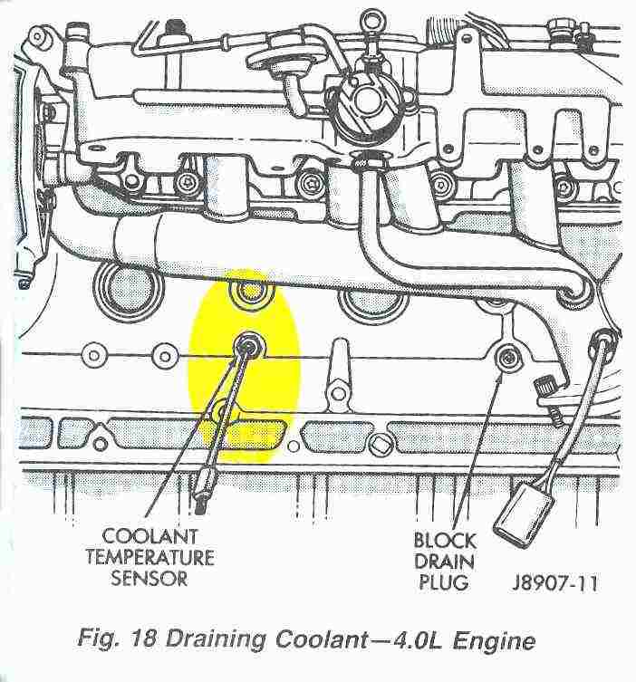
Located in engine
coolant jacket on the driver's side of the block. To test, use a high impedance
volt-ohmmeter. Resistance should be less than 1000 ohms with a WARM engine
(examples = 212* would be about 185 ohms, 160* would be about 450 ohms, 100*
(not warm enough) would be 1,600 ohms).
> What does it do? Adjusts
the injector pulse widths (Colder coolant temperatures result in longer
injector pulse widths and richer air-fuel mixtures). Compensates for fuel
condensation in intake manifold. Controls engine warm-up idle speed. Increases
ignition advance when engine is cold. Energizes the EGR valve solenoid to
prevent flow of vacuum to the EGR valve.
Update:
Basically - this sensor functions by providing a resistance-to-ground circuit
that the computer (ECU) uses to determine how much fuel the engine requires.
(The hotter the coolant - the lower the resistance.) The resistance of the
sensor is read by the ECU which in turn adjusts the air/fuel ratio as close to
14.7:1 as possible. When a coolant temperature sensor fails (open circuit / no
continuity) the high / infinite resisitance will cause the ECU to falsely read
the max low temperature of -40 degrees F. The ECU then tells the injectors to
enrichen the fuel mixture because it thinks the temp is really cold when it
really isn't. A short to ground would cause a 'no-resistance' fault causing the
ECU to think the coolant air temperature was extremely hot and lean out the
fuel mix.
Unlike late HO engines; RENIX engines do NOT have a
combination coolant temperature sensor that also feeds the gauge! RENIX
vehicles use a SEPARATE sensor located on the back half of the head, driver
side (See bottom of page.)
Resistance chart for both Coolant Temperature
Sensor
-and-
Manifold Air Temperature
| Coolant
Temperature and Manifold Air Temperature Sensor Resistance
Values Approximate resistance your meter should show at the temperature shown in the chart. NO resistance indicates a 'short' to ground - can be the sensor but will usually be a wire where the insulation has been abraded. INFINITE resistance indicates an 'open / broken circuit. Can either be a broken wire or a bad sensor. |
||
| Degrees Fahrenheit | Degrees Celcius | Resistance in Ohms |
| -40 | -40 | 100,700 |
| 0 | -18 | 25,000 |
| 20 | -7 | 13,500 |
| 40 | 4 | 7,500 |
| 70 | 20 | 3,400 |
| 100 | 38 | 1,600 |
| 160 | 70 | 450 |
| 212 | 100 | 185 |
Manifold Air Temperature Sensor (MAT)
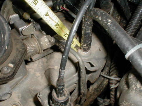 OEM location of MAT sensor is at end of tape measure. |
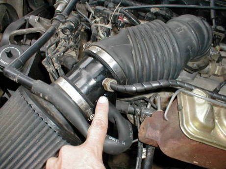 Relocated MAT sensor shown on Rusty's air tube. |
Installed in the top of the intake manifold. Testing is the same
as the CTS. Make sure engine is WARM.
> What does it do? Pretty much
the same thing as the CTS, but based off incoming air temperature.
Update: Basically - this sensor functions by providing a resistance-to-ground circuit that the computer (ECU) uses to determine how much fuel the engine requires. (The hotter the air in the intake manifold - the lower the resistance.) The resistance of this sensor is read by the ECU which in turn adjusts the air/fuel ratio as close to 14.7:1 as possible. When a manifold air temperature sensor fails (open circuit / no continuity) the high / infinite resisitance will cause the ECU to enrichen the fuel mixture because it thinks the temp is really cold when it really isn't. A short to ground would cause a 'no-resistance' fault causing the ECU to think the air temperature was extremely hot and lean out the fuel mix.
Manifold Absolute Pressure Sensor (MAP)
MAP sensor.  Located on driver side of firewall just behind & above engine. |
Located on firewall behind valve cover. To test, using a
voltmeter with the ignition on/engine off, voltage at terminal B should be 4 -
5 volts. The voltage should drop to 1.5 - 2.1 volts with a HOT, neutral idle
engine. Supply voltage can be checked at terminal C with the ignition on.
Voltage there should be 5 volts + or - 0.5 volts (Terminal A is the ground
wire).
> What does it do? Compares ambient barometric pressure
during start-up (cranking) to engine load while engine is running. The ECU
computes that information and adjusts the air-fuel mixture accordingly.
Here's a video of a YJ owner testing his MAP sensor.
Throttle Position Sensor (TPS)
TPS and Idle Stepper Motor.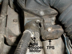 Located on throttle body facing toward radiator. |
Located on the right side of the front of the throttle body. To
test, disconnect the connector at the TPS. Check the voltage at TPS connector
pins B (Ground) and A (5.0 volt supply) with the ignition on. If you see about
5 volts, hook up the connector again. and check the voltage at TPS terminals C
(positive) and B (Ground) with the ignition on and the throttle plate closed.
You should notice approximately 0.8 volts. If you see that voltage, your TPS
and wiring should be ok. If not, you'll have to adjust the TPS to get that
voltage. If you cannot adjust the TPS to get that voltage, you'll have to
replace the TPS and adjust the new one properly. Also, with the voltmeter
hooked (terminal C) up and the ignition on, move the TPS arm down and back up
slowly and watch the voltage. The change should be increasing and smooth. If
there are any dead spots or it is not smooth, it probably needs to be
replaced.
> What does it do? The voltage is interpreted by the ECU to
determine current engine operating conditions. Just as a note to you, the
automatic transmission versions have 2 integral connectors (1 for ECU and 1 for
tranny). If you have the auto, make sure you're checking the right connector
(I'm not exactly sure what it looks like as I have the manual tranny).
Update: Suggestion: If you are having intermittant idle / surge issues and can't quite get the voltages to set right - before going out to buy a new TPS try checking your ground connection. Renix engines are notorious for having bad / faulty ground connections as a result of age and not so great design in the connectors. A common "fix" is to add a jumper ground wire from the TPS ground that bypasses the connector and harness entirely.
|
Idle Speed Stepper Motor - (aka Idle Air Controller / I.A.C.)
| |
Located on the left side of the front of the throttle body.
Testing requires the use of an "Ele. CT.01 exerciser tool". I don't have one
and don't know exactly what it does, but from what I've heard, it sounds like
it can actuate the motor to advance and retract the pintle. I'm not sure how
much that equipment costs, but I decided to just replace mine. I knew it was
operating, but wasn't sure if it was sticking at all, and it did have a slight
groove in it (the pintle) from use. I figured, the part is 12 years old and has
160,000 miles on it, it could probably use replacing. I had AutoZone order one
for me (I think it was about $65.00... I think they're about $125 from the
dealer). If you get one there, tell them you need the Idle Air Control Valve
for your vehicle or else they won't be able to find it in their database. The
new one I got works great.
> What does it do? The ECU uses it's
information and commands the unit to extend or retract the pintle, which
controls the amount of air which bypasses the throttle plate to maintain idle
speeds.
Here a 1991 YJ owner removes, cleans & replaces his Idle Air Controller. Note that it is different than the RENIX part but same location, same function and similar in appearance.
FOR HO THROTTLE BODIES ONLY!!! - Holley part #543-105 is an idle air control motor for Holley's pro-injection system and will swap for this part for around $28 at AutoZone vs. $125+ at the dealership! |
Oxygen Sensor
Located in the exhaust manifold. To test, using an ohmmeter,
disconnect the O2 sensor connector. Connect the ohmmeter test leads to
connector terminals A and B of the sensor connector. Resistance should be
between 5 and 7 ohms. Replace the sensor is the ohmmeter displays and infinite
reading. I don't know about you, but this test is pretty vague. They say it
should be between 5 and 7 ohms, but infinite is bad. What if you get a reading
of 13 ohms or 100 for that matter? I wasn't too fond of this test as I found it
is a test of the O2 sensor heating element!. One other thing you can do with
the O2 sensor is hook up the voltmeter to terminals B and C (I can't remember
if those are the right letters, but you want to get the sensor wire (believe it
was blue) and the ground wire, or just ground to something else) with the
connector hooked up and the engine on, warm, and idling. You should notice the
voltage jumping up and down in about 2 second or less intervals. If it doesn't
jump up and down considerably or takes longer than 2 seconds to do so, change
it.
> What does it do? The ECU interprets the voltage from this
sensor which analyzes the oxygen content on the exhaust gas and varies the
air-fuel ratio accordingly.
EGR Solenoid
EGR Solenoid. NOTE! This is NOT the EGR valve! Where applicable (RENIX systems) the EGR valve is located on intake manifold. The white object to the valve's right, held in place w/ a single screw in it's center 'nub' with the two orange wires going into it is the ceramic fuel pump ballast resistor. The ballast resistor is a source of intermittant stalling / hard start issues as well. Cheap to replace... easy to break. |
Located on the driver's side fender toward the front of the
vehicle. It has a vacuum line going to and from it as well as an electrical
connector. To test, using a vacuum tester, first verify that vacuum is present
at the vacuum source connector (the one near the electrical connector). I think
it should be around 15 mm Hg at idle. If vacuum is present, remove the output
side connector (two port style) which goes to the EGR valve transducer (looks
like a small black UFO...hehe) Connect a vacuum gauge to output B (the one
closer to the unit... it's a little longer than the other output). Start and
idle the engine. There should be NO Vacuum present at that point. Disconnect
the connector from the solenoid. There should now be vacuum present at output
B. Hook up the connector again and rev the engine a few times. You should
notice vacuum when revving it. The engine must be HOT for this test.
> What does it do? The solenoid allows or denies the presence of vacuum to
it's output, which opens and closes the EGR valve.
EGR Valve
Located on the drivers side of the engine toward the rear. To
test, with engine running, take a screwdriver and open the valve (pull the rod
away from the engine). The engine RPM's should drop and engine should sound
like it's running like garbage (may even stall out). Release the valve and it
should return to normal. If not, it's getting stuck. Mine passed these tests,
but I guess it wasn't closing all the way and you really can't tell if it is or
not. I even took mine off and cleaned it/checked for operation while off the
vehicle. I had to replace mine. As far as the transducer goes, you can open
that up with a screwdriver (the plastic pieces are just snapped together). Like
I said, the rubber diaphragm was real beat in mine and the spring was pretty
much non existent as it was rusted to nothing. I'm not sure what affect the
transducer has on the system, but it comes with the new valve. Remember to get
a new EGR Valve gasket if you replace yours.
> What does it do?
Opens during certain conditions to allow exhaust gasses to run through the
combustion chamber to burn again and reduce emissions."
The above text was provided courtesy of Eric Giordano (JabaThaHut) on J.U. Please be sure to thank him for this easy to follow information!
More %#$$&)(* sensors!
After looking through the above list, I noticed that somehow the Knock Sensor, CAMshaft Position Sensor & the nefarious CRANKshaft Position sensor was left out! (*doh!*)
Here is a video showing some of the sensors.
Knock Sensor
Mounted on lower, driver side of engine block, this small piezo-electrical device tells the ECM to retard ignition timing when it detects engine 'ping' / knock. Often gets damaged when installing engines but looks ok externally. If damaged, it can tell computer to retard ignition intermittantly, under the wrong conditions or not at all and cause anything from rough running to allowing terminal pinging to go unchecked.
 OEM knock sensor from my 1990 XJ. |
 Connector plug view. Connection is identical to those on a fuel injector. |
 Generic replacements. NAPA 1990 XJ replacement - #DKS111 (Echlin) |
 Style that supercedes mine. Functionally identical to old unit & plugs right in. |
C.P.S. (Crankshaft Position Sensor)
(AKA: CKP and / or engine 'Speed Sensor' in some
Daimler-Chrysler publications.)
Do Not Confuse this with the CAM Position
Sensor located in the "distributor"! Make sure your counterdrone knows which
one you are talking about!
See THIS
LINK for Cam Position Sensor Information.
This is the BIG Kahuna of problems for people with no start, hard to start & stall out issues! You do NOT want to have this fail far from home, wheelin' alone, tools in the garage and no spare anyhow... heck, even if ya did have the tools, helpers and a spare it's a major pain to fix beside the trail! This thing is kinda like a serpentine belt; ya won't remember to replace it until it breaks! Unlike a serpentine belt, SOMETIMES.... just sometimes, ya can limp on home... maybe. The CPS should be a regular maintanence item for any Jeep owner but the change out interval is more likely related to heat & vibration rather than miles. If anyone knows the actual time interval recommended by the factory on these, please let me know and I'll amend this page.
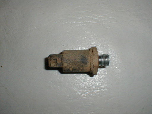
 View of uninstalled Crankshaft Position Sensor. |
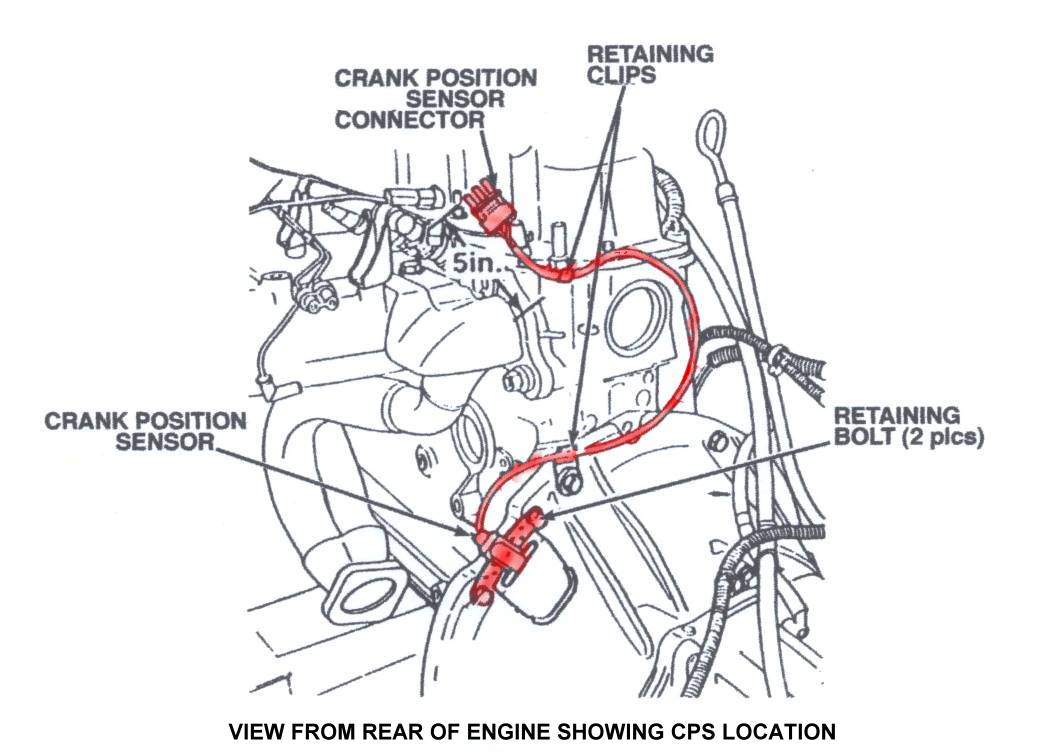 View of rear of engine showing Crankshaft Position Sensor & harness highlighted in red. |
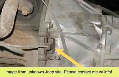 Great photo showing location of CPS on bellhousing. NOTE: I found this pic on my harddrive and have no clue where it came from. Had cyrillic writing on larger image & probably came from another Jeep site. I do NOT claim credit for this! Please contact for credit or removal. |
Here are a couple of videos to help you with that CPS / CKP test & replacement procedures.
CPS: You can check it's basic function but be aware that sometimes the darn things can be 'intermittant' but still read 'ok' when measured due to engine heat/temperature. Even so, these tests will show up a borderline CPS more often than not.
Check the connector first
If you've just
stalled out with same symptoms... unplug the CPS & plug it back in. If your
motor fires back up you might get off easy, but don't count on it lasting
forever. I dunno what doing this accomplishes other than cleaning the
connector contacts enough to let additional voltage through to the
computer. If unplugging & replugging worked then unplug the connector
again and clean those contacts off. Then apply some OX-GARD, or other
electrical contact cleaner & protectant (dielectric grease).
There
is a distinct possibility that you're not getting a signal due to a faulty
connector itself as well. Some people have cured their CPS problems by simply
cutting the connector out of the harness and SOLDERING the wires together (Use
heat shrink or electrical tape around the wire, of course!) Other's have
replaced the connector with a newer, waterproof version from an electrical or
automotive supply store.
Test#1 - Get a volt/ohm meter and set it to read 0 - 500 ohms. Unplug the cps and measure across the CPS connector's A & B leads. Your meter should show a CPS resistance of between 125 - 275 ohms. If it's out of that range by much; replace it. (* - Note: HO engines are measured from the B & C connectors and should have near zero ohms.)
Test#2 - You'll need a friend to help ya with
this one.
Set your volt/ohm meter to read 0 - 5 AC volts or the closest AC
Volts scale your meter has to this range. Measure across the CPS leads for
voltage generated as your friend cranks the engine. (The engine can't fire up
without the CPS connected but watch for moving parts just the same!) The meter
should show .5 - .8 VAC when cranking. (That's between 1/2 and 1 volt AC.) If
it's below .5vac, replace it.
Desperate last ditch tip to get home or a few more miles from a failing CPS: - Other than the unplug/replug trick... MJR passed on a trick of using a flat bar and a hammer to 'adjust' the CPS by smacking the CPS bracket and forcing a weak CPS just a tad closer to the flywheel. This lets a weak CPS get a stronger pulse and hopefully generate enough voltage to feed a good signal to the computer again. WARNING! - If ya smack it too hard... it'll go in too far and the flywheel will eat the CPS! Start walking.
Either way, if it fails ANY of the tests... you should replace it and save your self some major pain later. If not, at least carry a spare CPS but be aware that it's a royal pain in the ass to change on a cold motor and ya really don't wanna do it at night, on the trail and with a hot motor if ya can help it!
UPDATE:CPS SENSOR
HARNESS REPLACMENT TECHNICAL BULLITEN IN PDF FORMAT.
This one is a
'last resort' fix if you've replaced the CPS already & it didn't fix the
problem. The issue is a crappy harness which this bulliten addresses through a
replacement of the actual CPS harness. (They call it a CKP harness for some
idiotic Daimler-Chrysler reason...)
Tech Tip: - To more easily remove & replace the CPS use a floor jack to support your transmission cross member, remove the two bolts & two studs (replace those with bolts if you break one), then lower the transmission cross member by about 1-2 inches. This will give you enough room to get your hands & tools in for the CPS work. (Especially if you have big hands!)
"Almost" Sensors...
RENIX Coolant Temperature GAUGE Sending
Unit Located at rear of head on driver's side. |
NOTE!: This is NOT the
Coolant Temperature Sensor used by the ECU for engine management!
This is
the temperature sending unit for the temperature guage or idiot light. It is
often removed to 'burp' air from the engine coolant. Late HO engines use a
'combination' sensor in the same location as the RENIX Coolant Temperature
Sensor in the block. (See first diagram at top of page.)
If you are still having problems and need 'word for word' advice then you really should get yourself a Factory Service Manual. MUCH better than a crappy Haynes or Chiltons manual! Just follow the link from the Downloads Page.
I'd also like to put a plug in for Cruiser54's great website! If you have a RENIX Jeep then visit CRUISER54's website! It is a phenomenal resource for RENIX owners.- Off-site link.
If you have pics of your own repairs or can suggest other methods - please contribute your ideas (and pictures) to this article!
|
|
|
Revised on:
December 27th, 2015 |