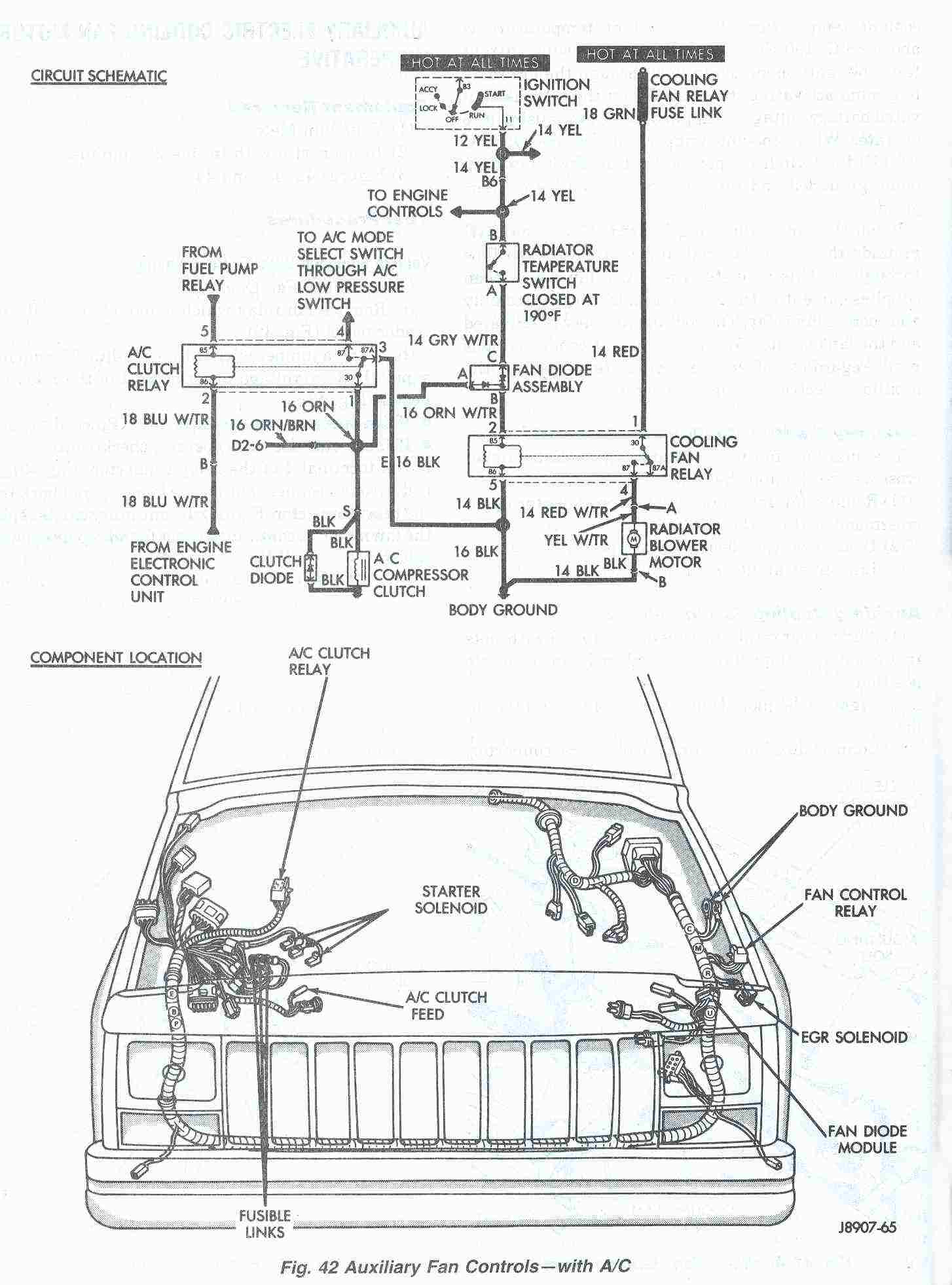
All MJ sand XJ vehicles equipped with a 4.0L engine that have air-conditioning and/or heavy duty cooling are also equipped with an auxiliary electrical fan. The fan is controlled by a relay mounted on the left inner fender panel. A switch attached to the radiator outlet tank above the radiator lower hose senses engine coolant temperature. When coolant temperature is above 190*F (88*C) the switch closes allowing current from the ignition switch to flow through the fan relay to ground activating the relay. When the relay is activated battery voltage is supplied to the fan causing it to operate. When coolant temperature is below 190*F (88*C) the switch is open preventing the relay from being grounded and the cooling fan from being energized.
When the air-conditioning is used the engine ECU grounds the A/C relay coil allowing current to flow through it. This activates the A/C relay which then supplies current to the A/C clutch, fan diode assembly and cooling fan relay. The cooling fan relay is activated and the fan operates. When ever the air-conditioning is used, regardless of engine coolant temperature, the auxiliary electric cooling fan operates.
Auxiliary Electric Cooling Fan Removal
The auxiliary fan is attached to the radiator upper crossmember behind the radiator.
- Remove fan retaining screws from radiator upper crossmember (Fig. 41).
- Disconnect the electric fan connector.
- Lift fan straight up out of vehicle.
Auxiliary Cooling Fan Installation
- Align lower retaining tabs of fan shroud with slots in bracket at bottom of radiator and push fan down into position.
- Tighten the mounting screws to 4.07 N•m (36 in- lbs).
- Connect auxiliary cooling fan electrical connector.
AUXILIARY ELECTRIC COOLING FAN MOTOR INOPERATIVE
Equipment Required:
- Volt/Ohm Meter
- Jumper wire with In-line 25 amp fuse
- Figures 42, 43, and 44.
Test Procedures For Vehicle Equipped With Air Conditioning
(1) Auxiliary Fan Operation:
- Remove fan relay which is mounted to left inner fender panel (Fig. 42).
- Using a jumper wire with an In-line 25 amp fuse, supply battery voltage to terminal 4 of the relay con- nector (Fig. 43):
- If fan operates, the motor is good. Proceed to (2).
- If fan motor does NOT operate, check continuity between terminal 4 of the relay connector (Fig. 43) and body ground connections on the fender panel back from the relay connector (Fig. 42). If continuity exists replace the fan motor. If continuity is not found repair open and retest.
(2) Cooling Fan Relay:
- With fan relay removed turn the ignition switch to the RUN position.
- Check continuity between terminal 5 of the relay connector (Fig. 43) and the body ground con- nections on the fender panel back from the relay con- nector (Fig. 42). If continuity exists proceed to next step. If continuity is not found repair open.
- Using jumper wire with In-line 25 amp fuse, jump across terminals 1 and 4 of the relay connector. If the fan motor operates proceed to next step leaving the jumper wire in place. If the fan motor does not operate repair fan relay fuse link. Refer to Wiring diagrams for circuit diagram.
- Check for battery voltage at terminal 2 of fan relay connector (Fig. 43).
- Connect a jumper wire across the radiator temperature switch harness connector. If fan operates proceed to next step. If fan does not operate replace radiator temperature switch once the engine has cooled down.
- Check for battery voltage at terminal 2 of the fan relay connector (Fig. 43). If battery voltage is not present replace the fan diode assembly.
Fan Inoperative When Air Conditioning Compressor Operates
With engine running, A/C on, and fan relay removed, check for battery voltage at terminal 2 of fan relay connector (Fig. 43). Replace fan diode assembly (Fig. 42) if battery voltage is not present. If battery voltage is not present perform (1) and (2) above.

Fig. 43 Auxiliary Fan Relay
Connector
Vehicle Not Equipped With Air Conditioning
(1) Auxiliary Fan Operation:
- Remove fan relay which is mounted to left inner fender panel (Fig. 44).
- Using a jumper wire with an In-line 25 amp fuse, supply battery voltage to terminal 4 of the relay connector (Fig. 43): • If fan operates, the motor is good. Proceed to (2). • If fan motor does not operate, check continuity between terminal 4 of the relay connector (Fig. 43) and body ground connections on the fender panel back from the relay connector (Fig. 44). If continuity exists replace the fan motor. If continuity is not found repair open and retest. (
2) Cooling Fan Relay:
- With fan relay removed turn the ignition switch to the RUN position.
- Check continuity between terminal 5 of the relay connector (Fig. 43) and body ground connections on the fender panel back from the relay connector (Fig. 44). If continuity exists proceed to next step. If continuity is not found repair open.
- Using jumper wire with In-line 25 amp fuse, jump across terminals 1 and 4 of the relay connector (Fig. 43). If the fan motor operates proceed to next step leaving the jumper wire in place. If the fan motor does not operate repair fan relay fuse link. Refer to Wiring diagrams for circuit diagram.
- Check for battery voltage at terminal 2 of fan relay connector (Fig. 43).
- Connect a jumper wire across the radiator temperature switch harness connector. If fan operates proceed to next step. If fan does not operate replace radiator temperature switch once the engine has cooled down.
- Check for battery voltage at terminal 2 of the fan relay connector (Fig. 43). If battery voltage is not present replace the fan diode assembly.
If you have pics of your own repairs or can suggest other methods - please contribute your ideas (and pictures) to this article!
|
Revised on:
January 9th, 2007 |